
I welcome you to the MLCAD
Tutorial. I hope that MLCAD runs correctly and that the installation of
LDraw
is alright as well. If there are any problems left please have a look at
the homepages of these programs. If everything is ok we can start immediately.
Together we learn about MLCAD's basic functions and we will use them
to build a small Lego model - lets say
"Learning by Doing".
Well, lets run MLCAD and we will have a look at the graphical user
interface. If you start up the program for the first time, you are confronted
with the setup dialog. If there is a problem please check the MLCAD
homepage!
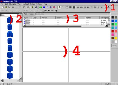
The graphical user interface should look like this or a little bit different.
Possibly the toolbars are at another position. You can position them
anywhere on the desktop you want. It is an good idea to do so.
The main window can be divided in 4 areas. I have marked them on the
screen copy with the red numbers.
Area 1 combines menubar and the different toolbars. The paint palette
on the right side of the main window belongs to this area as well. With
the help of area 2 you choose the Lego parts for the model. In area 3 the
phases of the Lego model are organized. Later you can make a real building
instruction known from the original Lego models. The construction of the
model is done in area 4. Here you can see the model from 4 different perspectives.
Lets click on a part in area 2 and drag it to area 4 by holding the
left mouse button down. In area 4 you release the button. Congratulations
- you have inserted a part for the Lego model for the first time.
![]()
Move the part in area 4 in all directions. To do this you have to click on the part and drag it by holding the left mouse button. You can also move a part by using the shown buttons in the toolbar. For practise you should drag some more parts to area 4 and get more familiar to the different perspectives.
If you stop moving the mouse over a part in area 2, you can read some information about the part at the bottom of the screen. "3005.DAT / Brick 1 x 1" would tell us that the name of the part is "Brick 1 x 1" and that all information about the part is saved in the file "3005.DAT". You should try to learn the names of the parts, because it is easier to find them in area 2 by name.
If the view of the parts in area 4 is very small you can zoom it. Click on the shown symbol in the toolbar. MLCAD will zoom all parts to a fitting size automatically.
Everytime you add another part to area 4, the new part will be listed
in area 3. All information about this part like position, rotation,
colour and description are combined there. If you click on a part in area
3 the part will be marked up.
![]()
Around a marked part is a black rectangle and in the middle of the part
is a white cross. In the illustration on the left the red part is marked
and the black one is not.
The order of the parts in area 3 is like the building order. If you
mark a part, all other parts under the marked part will not be shown. That
is a feature for all slow computers. If you want to see all parts the whole
time, you have to deactivate the option "Draw to selected part only" in
the setup dialog under "Settings".
If you like to delete a part in area 4, you have to mark it. Press the delete key on your keyboard and the part will disappear.
Before we start building our small model, I would like to tell you another thing. A part's freedom of motion is limited by an invisible grid. In MLCAD you have the choice between 3 different grids. You can choose them from the toolbar with the shown symbols. You should work with the middle grid, because it is based on the size of Lego parts.
Let's start a new model. You have to choose "File|New" from the menubar
or press "Ctrl+N". If the program asks to save our first steps, you should
deny this.
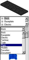
This should be the first part for our small model. We have to search
it in the partlist in area 2. The part's name is "Plate 2 x 6". We
open the shown popup menu and choose the category "Plate" with the mouse.
MLCAD shows us the parts in a 3D view. With the help of the scrollbar
we can scroll the list down to see more parts. After about the half we
will find the part "Plate 2 x 6". We drag it to area 4.
The search for the parts in area 2 is like the rummage in the Lego
box. In area 4 the model is constructed.
There is another possibility to set the position of a part. You have
to mark the part in area 4 and press the right mouse button. A small menu
will appear where we have to choose "Enter Position...". In the dialog
you should enter the values -75, 40 and 0 (x, y, z) for our model.
Actually it is not important where to start with the construction of the
model. I just wanted to show the different possibilities to change the position
of a part.
Before we get to the next instruction step, we will tell the program, that we finished this step. Therefor we mark the "Plate 2 x 6" in area 3 and press the right mouse button. A small menu will appear and we choose "Add Step". I will explain later why we have done this...
For the next step we need 3 new parts:
| Number | Colour | Part | Description |
| 1 | Black | 3839.DAT | Plate 1 x 2 with Handles |
| 1 | Black | 3936.DAT | Wing 4 x 4 Left |
| 1 | Black | 3935.DAT | Wing 4 x 4 Right |
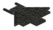
The first part is in the category "Plate", the other parts are under
"W" like "Wing". During the positioning of the plate should be no problems.
But both wings are not correctly rotated.
You can influence the orientation of a part in 2 different ways. Mark
the part in area 4 and click with the right mouse button on it. Choose
in the menu "Enter Rotation...". You can change the orientation with the
correct values.
![]()
But it is easier to use the toolbar. With the shown symbols you can
rotate the marked part in any direction along the coordination axis. The
value of rotation is influenced by the chosen grid. If you use the middle
grid, the part is rotated by 45deg; for each click.
To position the parts more exactly you should zoom the view with
the help of the toolbar like described above. You can
also zoom each window in area 4 itself by pressing the right mouse button
and choosing "Zoom". The rest would be selfexplaining...
Let's mark this building step as finished. We click on the last added
part in area 3 and add with the help of the right mouse button another
"Step".
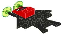
In the next step we need 4 parts:
| Number | Colour | Parts | Description |
| 1 | Red | 3298P68.DAT | Slope Brick 33 3 x 2 with MTron Logo Pattern |
| 2 | Trans-Light-Green | 4740.DAT | Space Radar Dish 2 x 2 |
| 1 | Black | 4859.DAT | Wedge 3 x 4 Plate |
In the upper part of area 2 we could search for a special part by name.
The first part of this step can be found in the category "S". To search
for a part in that way is very fast, because the different parts have not
to be drawn in area 2.
Before we can give a part a colour, we have to add the part to our
model - we have to drag the part from area 2 to area 4. We press in area
4 the right mouse button and choose "Change Colour...". In the appearing
dialog we have to choose the colour for the part and then press the
"OK"
button.
For the red part I used the red in the top line. I have given the green
with the colour number 42 to the parts with the light green transparent
colour. You will find the colour lower in the paint palette. You can browse
the paint palette with the help of the scrollbar on the right of the window.
If you like to give a standard colour to a part, you can select the
colour directly from the main window. You have to mark the part and then
choose the right colour from the paint palette.
Before we go on, we should add a "Step" in area 3 after the last part
added. If you does not remember how to do please look above.
We have not saved our model until now. We are going to do this immediately.
We have to choose from the menubar "File|Save As...". In the dialog we
give a directory and a name (a good name would be "tut_vec.dat")
to the file. But I think you know the functions of this dialog from the
work with Windows.
Open the file by choosing from the menubar "File|Open..." and check if the file was really saved. Try to add another part to the model - it would not work!
MLCAD works in two different modes, as all original Lego models have
2 main parts. In one mode we can build our model. In reality this would
be the building of the Lego model. In the other mode we can view the building
instruction, which belongs to every Lego model. If you load a model, you
always will be in the building instruction mode.
![]()
By the help of the shown symbols you can view the different building steps. All parts to the next "Step" will be shown. With the "Steps" we have marked the end of a building step. These steps are not really needed, if you do not want to generate a building instruction.
But our model is not complete and we want to go on building. We have
to change to the edit mode, by clicking on the shown pen in the toolbar.
With this symbol you shift between edit and building instruction mode.
Please play around to understand the difference.
![]()
Before you go on building, you have to mark the last "Step" in area
3 by clicking with the mouse on it or using the shown arrow from the toolbar.
For the next step we need the following parts
| Number | Colour | Part | Description |
| 1 | Black | 2452.DAT | Hinge Plate 1 x 2 with 3 Fingers On Side |
| 2 | Red | 2450.DAT | Plate 3 x 3 without Corner |

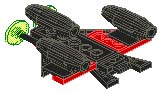
The construction of the new parts should be no problem. We try to rotate the whole model for the building instruction. In a original Lego building instruction the model is also rotated, if it is better for the building view.
MLCAD has to know when the model should be rotated and in what direction. Before a new part is added to the model, we rotate the whole model first. We have to mark the last "Step" in area 3 and then press the right mouse button. From the menu we choose "Add Rotation Step...". A dialog will appear. Here we can describe the rotation in degrees. To check the effect of all these numbers, we can press the "Preview" button. MLCAD will show us the new orientation of the model. For our tutorial we enter the value 180 for "X" and activate the option "Relative". We leave the dialog by pressing the "OK" button.
The model will have the new orientation, until we add another rotation
or we stop the new rotation. We can add the new parts and finish this step
by adding a new "Step" to area 3.
The new orientation won't be shown in area 4. If we want to see our
model from below, we have to press the right mouse button in one of the
4 windows. From the appearing menu we choose "View Angle" and than "Below".
You should save the model and view the building instruction by clicking
on the pen in the toolbar.
The next instruction step is very easy and there is not anything new
for you. Please do not forget to add a "Step" at the end of this building
step. Here are the parts:
| Number | Colour | Part | Description |
| 3 | Black | 4229.DAT | Plate 2 x 2 with Jet Engine |
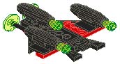
This step looks easy as well. Please do not forget to activate the option
for transparency!
| Number | Colour | Part | Description |
| 3 | Trans-Light-Green | 4589.DAT | Cone 1 x 1 |
While trying to position the "Cones" in the middle of the "Jet Engines"
you will get into trouble. It is not possible. To solve this problem you
have to choose another grid. Please activate the right grid symbol in the
toolbar and try again. If you do not remember the grid symbols, please
look above.
If you have added the 3 new parts, you should change back to the middle
grid and add another "Step".
We have finished work under the model and we can rotate it back. Therefor
we mark the last "Step" in area 3 and add with the help of the mouse (right
mouse button) an "Add Rotation End Step". If you view the building
instruction, you will notice that MLCAD rotated the whole model back.
For the next parts the orientation is very important. I can not
describe this - you have to try on your own.
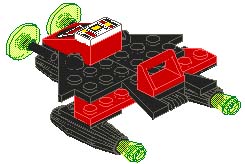
Please do not forget the yellow marked parts!
| Number | Colour | Part | Description |
| 2 | Black | 298.DAT | Lever Small Base |
| 1 | Red | 2432.DAT | Tile 1 x 2 with Handle |
| 1 | White | 3069P68.DAT | Tile 1 x 2 with Red & Yellow Controls Pattern |

Naturally the control sticks should lay in the hands of the mini figure.
But do not try too hard, because there is no mini figure yet.
| Number | Colour | Part | Description |
| 1 | Black | 4276.DAT | Hinge Plate 1 x 2 with 2 Fingers |
| 2 | Red | 4593.DAT | Lever Small |
It would be easier, if you only add one antenna with the right orientation
and then make a copy of it. Therefor you have to mark the first antenna
and choose from the menubar first "Edit|Copy" (Ctrl+C) and then "Edit|Paste"
(Ctrl+V). The new antenna is on the same place with the same orientation
- both antennas overlap eachother. Now you can move one antenna to the
new place. This should be faster than orientating both antennas on their
own.
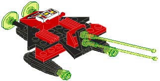
| Number | Colour | Part | Description |
| 2 | Trans-Light-Green | 2569.DAT | Antenna Whip 8H |
| 2 | Red | 2412.DAT | Tile 1 x 2 Grille |
We have finished the space vehicle. If you like you can compare it with
my
version of the space vehicle.
We have finished our model. I hope you added after each building step
a "Step" in area 3. The only thing we need for our model is a fitting mini
figure.
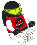
The construction of a figure works like the construction of the model,
because the mini figure is made of normal Lego parts. You will find most
of the parts in the category "M". Save the space vehicle and start a new
model with "File|New".
If you finished the construction of the figure, you have to save it.
("fig_tut.dat"
would be a good name) Here is the part list for the figure and
two other perspectives.

| Number | Colour | Part | Description |
| 1 | Black | 970.DAT | Minifig Hips |
| 1 | White | 971.DAT | Minifig Leg Right |
| 1 | White | 972.DAT | Minifig Leg Left |
| 1 | Black | 3838.DAT | Minifig Airtanks |
| 1 | Yellow | 3626BP01.DAT | Minifig Head with Standard Grin Pattern |
| 1 | Black | 2446.DAT | Minifig Helmet |
| 1 | Trans-Light-Green | 2447.DAT | Minifig Helmet Visor |
| 1 | Red | 973P68.DAT | Minifig Torso with MTron Logo Pattern |
| 1 | White | 976.DAT | Minifig Arm Left |
| 1 | White | 975.DAT | Minifig Arm Right |
| 2 | Black | 977.DAT | Minifig Hand |
To add a "Step" after each building step is not important during the
building of a mini figure. If you do not want to build the mini figure
by yourself you can download my version.
It does not seem to be very useful to save mini figure and model
in two different files. Because we want the figure sitting in the space
vehicle or standing beside. For this problem MLCAD gives us the possibility
to combine different models in one file. But we will be able to change,
rotate and move the different models independently to eachother. We can
also view the different models all together in one picture.
For that we have to do the following. Load the mini figure or the space vehicle. Choose "Multipart|Import Model..." from the menubar. In the dialog you should choose the other part for our model. Both models are loaded independently to eachother.
You have the possibility to change between the different models with
the help of area 3. We want to view both models at the same time.
We have to add a new model by choosing "Multipart|New Model..." from
the menubar. In the appearing dialog we should insert in the first edit
field e.g. "tutorial" and in the second one e.g. "Space Vehicle and Figure".
We have to close the dialog by pressing the "OK" button.
The new model is empty. But our 2 parts are in area 2 in the category "Document". We can drag them into our new model. The models are handled like a real Lego part.
Place the mini figure into the space vehicle. If the position of the arms or hands are not correct, you change back to the figure's model by help of area 3 and make the hands fitting and so on. If you change back, you will see, that your model has been updated with the changes.
We have to save the whole thing. We choose from the menubar "File|Save As...". The file will have the extension "mpd". For the tutorial model you can download the file here.
This all seems to be very complex. But if you understand it, you will have a great tool to manage big scenes with a lot of different models.
If you need the files of the different models, you can generate them
by choosing "Multipart|Export Models..." from the menubar.
Let's generate a building instruction and a part list for our Lego
model. First we activate the space vehicle in area 3. The building instruction
will be generated by MLCAD by choosing "File|Save Pictures..." from the
menubar. We have to choose a resolution for the pictures. The option "Pictures
for every step" should be activated - the option "Pictures for all sub-models"
should be deactivated. We leave the dialog by pressing the "OK" button.
We have to give a name for the building instructions.
The generations for the mini figure is done the same way. We can view the complete building instruction with an external image viewer.
I think we want to make a snapshot of our model. We activate the complete model in area 3 and choose "File|Save Pictures..." from the menubar. This time we activate the option "Snapshot". If we check the option "Pictures for all sub-models", MLCAD will generate a picture for the figure, for the space vehicle and for both together.
At the end we generate a part list by choosing "File|Save
Partlist..."
from the menubar. We give a name to the file. You can download
the tutorial's partlist.
We had a look at the different functions of MLCAD. I think it should
be no problem for you to build your own models. Maybe you will need some
practise, but practise can not be taught.
The real fun starts with a finished model. You can convert the files
to the free 3D rendering program Povray.
You can make movies with your own Lego models. A good converter from DAT
to POV was written by Lars
C. Hassing.
MLCAD's author Michael Lachmann is interested in any bugs or suggestions. I am too. So please help me developing and improving the tutorial!
A very big thank-you goes to Rob Goudvis, who helped me correcting all the grammatical mistakes in the English version of this tutorial.
You can send an email to me or visit the homepage of my friends and me!
I hope you had some fun during the tutorial and it helped you starting to design Lego models with MLCAD and the computer.
Sebastian Stein